
© by Tony van Roon,
VA3AVR
"SCR's and Triacs are high-speed, solid-state switches used in AC and DC power
control applications. Find out how they work and practical applications for them."
 What Exactly are Triacs or SCR's? They are
similar and function similar. The difference is that triacs are usually involved with the ac side and scr's with the
dc side. Triac circuits can be used to control line-voltage (AC) powered devices.
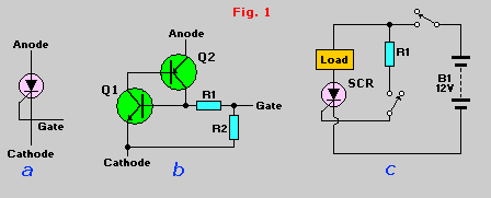
SCR's and Triacs are both members of the the thyristor family. The SCR (Silicon Control Rectifier), is a four-layer (PNPN) sandwich of semiconductor
material. Its symbol is shown in Fig. 1-a, and its equivalent circuit is shown in
Fig. 1-b. The circuit is a complementary regenerative switch in which Q1's base current is
derived from the collector Q2, whose base current is in turn derived from the collector of Q1. We'll discuss that
regenerative action in much greater detail shortly.
Fig. 1-c show the basic circuit that lets you use
the SCR as a switch in a DC power-control circuit. The circuit works as follows. When power is first applied to the
SCR by closing S1, the SCR is "blocked" and appears as an open-circuit switch. That action can be understood by
examining Fig. 1-b, where is can be seen that, because Q1's base is shorted to the
cathode terminal via R1 and R2, Q1 is cut off through lack of base current. Therefore Q1 feeds no base current to Q2,
so it is also cut off. Because both transistors are cut off, only a small amount of leakage current can flow between
the anode and cathode terminals.
 The SCR can
be turned on (made to act like close switch or a forward-biased silicon rectifier) simply by applying a positive gate
current. That can be done in the circuit shown in Figure 1-c simply by closing S2. The gate current thus
applied causes the SCR to switch on very quickly.
If the externally applied gate current is sufficiently large, it will cause Q1 to
start to turn on. As it does, its collector current feeds Q2's base, thereby causing Q2 to turn on and feed additional
base current to Q1, and so on. The way in which the two transistors feed each other is called regenerative switching.
After the SCR turns on and is conducting significant forward current, the SCR
stays on even if the gate drive is subsequently removed. Therefor, only a brief pulse of gate current will be needed
to latch the SCR on. Note in Fig.1-b that because of the presence of R1 and R2, the SCR cannot be turned of by
shorting and reverse-biasing the gate-cathode terminals of the device.
In fact, the only way of turning the SCR off is by momentarily reducing its anode
current below a value know as the minimum holding current (IH). So it follows that turn-off occurs
automatically in a AC circuit near the zero-crossing point at the end of each half cycle.
 A finite amount of internal capacitance exists between anode and gate of an SCR.
Consequently, if a sharply rising voltage is applied to the anode, that internal capacitance can cause part of the
rising voltage to break through the gate and thus trigger the SCR on. That "rate effect" turn-on can be cause by
supply-line transients, and it sometime occurs at the moment when power is applied to the SCR's anode. Rate-effect
problems can usually be overcome by wiring a simple RC "snubber" network between the anode and the cathode of an SCR;
the network limits the rate-of-rise to a safe value.
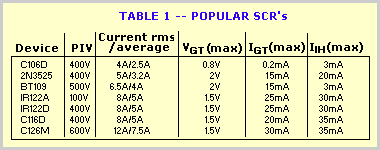
Those are the basic characteristics of the SCR. As you can see, it's a fairly simple device. When choosing an SCR for
a particular application, you'll usually find that the most-significant parameters are the peak voltage and current
rating the gate sensitivity rating, and (occasionally) the value of the device's minimum holding-current. Table 1
lists basic specifications of several popular SCR's.

 Basic DC Circuits:
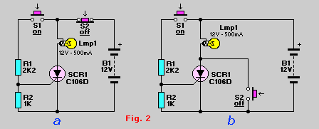
SCR's are used in both AC and DC power-control circuits; let's look first at some basic DC circuits. Two ways of
using the SCR as a pushbutton-controlling power-switch are shown in Figure 2. In both circuits, the SCR (and thereby
the lamp) can be latched on by momentarily closing S1, thereby feeding gate drive to the SCR via R1. In both circuit
the gate is tied to the cathode via R2 to improve stability of the circuit.
Of course, after the SCR turns on, it can be turned off again only by momentarily reducing anode current below the
device's IH value. In Fig. 2-a the SCR is turned off by momentarily opening S2; in Fig. 2-b
is that done by using S2 to short the anode and cathode terminals of the SCR momentarily.
Figure 3 shows another way of turning the SCR off. Here, after the device turns on, C1 charges up to almost the full
supply voltage via R3 and the anode of the SCR. When S2 is subsequently closed, it clamps the positive end of C1 to
ground, and the charge on C1 forces the anode of the SCR to swing negative momentarily, thereby reverse-biasing the
SCR and causing it to turn off. The capacitor's charge bleeds away rapidly, but it has to hold the SCR's anode
negative for only a few microseconds to ensue turn-off. Note that C2 must be non-polarized type.
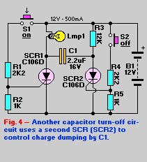
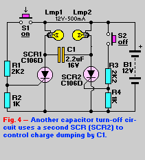
A variation of the capacitor turn-off circuit ishown Fig. 4. A slave SCR (SCR2) replaces the turn-off switch (S2) in
Fig. 3. The master SCR (SCR1) is turned off by briefly turning on SCR2 via S2. The slave SCR turns off after S2 is
released, because the anode current provided by R3 is lower than SCR2's holding current.
Testing an SCR:
This simple SCR tester can be made with only a couple components. It will provide a visual 'go' or 'no-go' indication
on the cheap--it is simply a voltage source, a lamp, and a resistor through which gate current is supplied.
 This handy tester will provide a visual "on" or "off" switching and latching indication. When finished, you can test
all those posible 'duds' in your junkbox and dump some of those in the garbage. If the scr is latching and can hold
the latch it is most likely okay.
Look at the circuit diagram, it shows a 3-amp, 50-volt SCR (under test) and a test circuit. Points "Gate" and
"Kathode" are temporary connections, so that they can easily be opened. I used toggle switches for each, but use
whatever you feel comfortable with, a simple jumper wire would do the trick. I use this gadget in my shop and so
have it mounted in a small case. This circuit can even be bread-boarded for your purpose.
When "Kathode" is closed, the lamp doesn't light. When "Gate" is also closed, the lamp lights to its full
intensity. The lamp remains lit even if "Gate" is opened again. But when "Kathode" is opened, even momentarily,
the lamp does not close again when "Kathode" is closed. That illustrates the "ON" and "OFF" operation of the SCR.
I tested the following SCR types: C106D1 (400V/4A)         T106Y1 (30V/4A)
                                  C106F (50V/4A)           C106F1 (50V/4A)
                                  C106B (200V/4A)          CSM2B2 (100V/4A)
                                  T106D1 (400V/4A)         NTE5402 (100V/0.8A)
                                  TIC106M (600V/8A)        NTE5457 (400V/4A)
                                  TIC126M (600V/25A)       CR6AM-8 (400V/10A)
                                  MCR106-3 (100V/4A)       NTE5455 (200V/4A)

In all cases the tester was accurate in telling 'good' from the 'bad'.
TRIACS:
I decided to experiment the tester on TRACS since they operate on the same principle. The pin-out of a Triac is usually
MT1, MT2, and Gate. Hookup the probes as follows: The 'K' probe to 'MT1', the 'A' probe to 'MT2' and the 'G' probe to
'Gate'. I used a 9Volt and a 12Volt power-supply for bench testing purposes. Execute the tests the same way as a SCR.
The lamp should only be on when the K switch is on and G switches on momentarily. In any other condition the
lamp should remain off. If not, the Triac will almost certainly be defective. Keep the tests on any Triac as short
as possible.
I tested the following Triacs with good results:

     Q4006L4  (400V/8A)  - Tested Good (was new)
     Q6006LT  (600V/10A) - Tested Defective  (was defective)
     Q6010L5  (600V/10A) - Tested Good (was new)
     L4004F31 (400V/4A)  - Tested Defective  (was defective)
     MAC15A   (400V/15A) - Tested Good (was new)
     NTE5610  (800V/8A)  - Tested Good (was new)
Again, in all cases the tester was correct. I compared the results of the two defective Triacs with the results of a
very expensive commercial SCR/Triac tester. On the commercial tester you can set the actual VRM (volt) of a Triac and
check for leakage and what not but I found the end result the same; "is it good or bad" and is it "switching or not".
Here is another way to test a Triac: Testing a Triac
Suggested Reading:
Copyright and Credits:
"Using Triacs and SCR's" by Ray Marston, Radio Electronics Magazine, September 1987.
(Hugo) Gernsback Publishing is (sadly) out of business.
Re-posting or taking graphics in any way or form of this project is expressly prohibited by international copyright
© laws. Permission to copy by written permission only.
Copyright © 2003 - Tony van Roon, VA3AVR
Last updated: September 02, 2010


 What Exactly are Triacs or SCR's? They are
similar and function similar. The difference is that triacs are usually involved with the ac side and scr's with the
dc side. Triac circuits can be used to control line-voltage (AC) powered devices.
 The SCR can
be turned on (made to act like close switch or a forward-biased silicon rectifier) simply by applying a positive gate
current. That can be done in the circuit shown in Figure 1-c simply by closing S2. The gate current thus
applied causes the SCR to switch on very quickly.
 A finite amount of internal capacitance exists between anode and gate of an SCR.
Consequently, if a sharply rising voltage is applied to the anode, that internal capacitance can cause part of the
rising voltage to break through the gate and thus trigger the SCR on. That "rate effect" turn-on can be cause by
supply-line transients, and it sometime occurs at the moment when power is applied to the SCR's anode. Rate-effect
problems can usually be overcome by wiring a simple RC "snubber" network between the anode and the cathode of an SCR;
the network limits the rate-of-rise to a safe value.


 This handy tester will provide a visual "on" or "off" switching and latching indication. When finished, you can test
all those posible 'duds' in your junkbox and dump some of those in the garbage. If the scr is latching and can hold
the latch it is most likely okay.